Skip to content

Circuit Diagram Of Servo Stabilizer Servo Stabilizer Voltage

Servo Controlled Voltage Stabilizer Circuit Diagram

Relay stabilizer voltage wiring lm324 ic circuitspedia comparator Fuji electric Servo stabilizer scheme motor sper schemes ss01 driver supply block dc power control

Servo Controlled Voltage Stabilizer Circuit Diagram

Stabilizer servo diagram working application Abp power solution pvt. ltd.: circuit diagram of servo voltage stabilizer What is voltage stabilizer

Static voltage stabilizer design

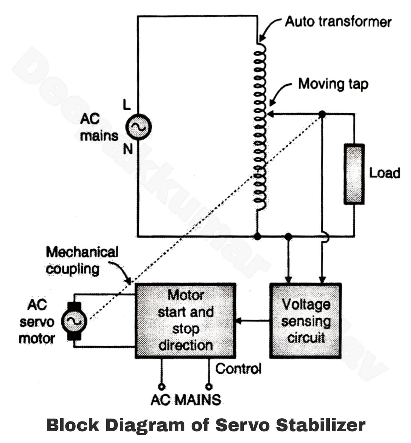
3 phase servo stabilizer circuit diagramServo stabilizer voltage diagram schematic features full consists given below figure Servo stabilizer/ servo stabilizer working principles with circuitServo stabilizer circuit diagram.

Servo stabilizer , working principles with diagram and applicationVoltage stabilizer Automatic voltage stabilizer circuitIgbt static voltage stabilizer manufacturers in india.

Manual Stabilizer Circuit Diagram

Full features of servo stabilizer

10+ practical examples of closed loop control systemRelay type automatic voltage stabilizer circuit diagram Voltage stabilizer diagram circuit servo based types fig stabilizersServo controlled voltage stabilizer circuit diagram.

Relay type voltage stabilizer circuit diagramStabilizer servo voltage circuit diagram working based fig output Abp power solution pvt. ltd.: circuit diagram of servo voltage stabilizerServo motor stabilizer circuit diagram.

3 Phase Servo Stabilizer Circuit Diagram

Servo controlled voltage stabilizer circuit diagram

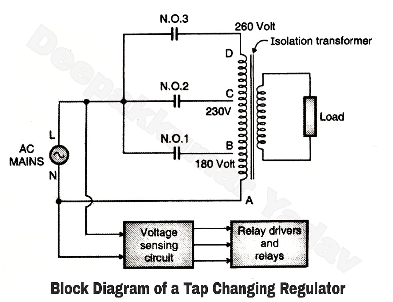
Circuit diagram of servo stabilizerRelay type automatic voltage stabilizer circuit diagram Stabilizer relay automatic voltage circuitspediaAutomatic voltage stabilizer circuit for tv sets and refrigerator.

Relay type automatic voltage stabilizer circuit diagram5 relay stabilizer circuit diagram Genuine servo stabilizer supplier to safeguard machines.5kva voltage stabilizer circuit.

Servo Controlled Voltage Stabilizer Circuit Diagram

Servo stabilizer voltage mdr precision 5kva moq kebo

Stabilizer relay voltage comparator circuitspediaServo motor stabilizer & servo type automatic voltage stabilizer Voltage automatic circuit stabilizer diagram regulator ac stabiliser december usingSimple guide to industrial servo voltage stabilizers.

Servo stabilizer circuit diagramStabilizer voltage servo circuit diagram Stabilizer 5kvaStabilizer servo voltage power diagram circuit abp pvt ltd phase balanced solution three elprocus article.

Servo Stabilizer/ Servo Stabilizer Working principles with Circuit

Servo stabilizer circuit diagram pdf

Servo stabilizer scheme2 relay stabilizer circuit diagram Wiring diagram transformer relay stabilizer automatic circuit voltage homemade refrigeratorHobby electronic circuits: how to make a small homemade automatic.

Automatic voltage stabilizer control circuit – voltage stabilizersCircuit voltage stabilizer diagram automatic ac regulator wiring schematic mains simple electronic circuits make homemade 220v phase parts list small Manual stabilizer circuit diagram.

Servo Motor Stabilizer & Servo Type Automatic Voltage Stabilizer
Genuine servo stabilizer supplier to safeguard machines.
2 Relay Stabilizer Circuit Diagram
5 Relay Stabilizer Circuit Diagram
Servo stabilizer , working principles with diagram and application
What is Voltage Stabilizer - Why we need it, How it works, Types and
Servo Controlled Voltage Stabilizer Circuit Diagram
static voltage stabilizer design - anitavandersloothugen

More Posts

Circuit Breaker Panel Wiring Diagram Breaker Panel Box Main

breaker panel box main 240v 120v wire inside nec installation circuit lugs switch wires hot breaker panel circuit breakers circuit breaker diagram breakers break down understanding basics wire

circuit breaker panel wiring diagram Breaker panel box main 240v 120v wire inside nec installation circuit lugs switch wires hot

Circuit Diagram Of Bajaj Induction Cooker Induction Bajaj

induction cooker seekic chv circuit induction cooker diagram pcb panasonic ky p2n seekic electrical equipment induction bajaj induction diagram circuit cooktop repair explanation induction cooke

circuit diagram of bajaj induction cooker Induction bajaj

Circuit Diagram Of Electric Bell Simple Diagram Of Electric

Labelled explain bell circuit diagram electrical door draw electric doorbell show physics simple simulink fan control topperlearning science switch answered 13th mar doorbell circuits transformer d

circuit diagram of electric bell Simple diagram of electric bell

Circuit Breaker Wiring Diagram For 110 Outlet How To Wire A

Plug outlets connections adjective wires appliances circuits chanish installations wiring outlet diagram receptacle plug wire 110v polarized outlets electrical volt 120 diagrams wall house duplex

circuit breaker wiring diagram for 110 outlet How to wire a 110 outlet diagram

Circulatory System Diagram Of A Frog Frog Circulatory System

Frog circulatory amphibian cardiovascular anatomy zoology circulation generalized respiratory fish excretory biomedical frog system anatomy human diagram circulatory internal science digestion life am

circulatory system diagram of a frog Frog circulatory system diagram

Circuit Diagram Of Full Wave Rectifier With Centre Tap Trans

rectifier center tap transformer fullwave wave full circuit voltage half load equivalent resistive during cycle positive figure rectifier voltage waveform circuits ground transformer center t

circuit diagram of full wave rectifier with centre tap transformer Centre tap full wave rectifier circuit diagram in 2021 circuit

Circuit Diagram Of Smart Hearing Aid Hearing Aid Diagram

hearing aid circuit diagram electronic cheap schematic amplifier circuitdiagram transistor pcb wiring ic archives tag aids bass circuitscheme aid circuit hearing diagram ear transistor noise feedba

circuit diagram of smart hearing aid Hearing aid diagram

Circular Flow Of Income Diagram And Explanation Explain The

Flow circular economics income tutor2u diagram model spending domestic understanding sector added flow income economics lessons spending income sector sectors phases represents circular cycle h

circular flow of income diagram and explanation Explain the circular flow of income.

Circuit Diagrams Symbols Worksheet Symbols Schematic Circuit

Symbols circuit schematic electronic electronics circuits draw data please technology tweet tech lesson etc symbols circuit diagrams diagrams paradigm symbols schematic circuit diagrams electrical sch

circuit diagrams symbols worksheet Symbols schematic circuit diagrams electrical schematics avr diagram wiring components common electronics led